Thursday, November 20, 2014

Breadbroad

October 30, 2014

This is a simple circuit to light up a bulb and a resistor was used to prevent the light bulb from burning up.

This is similar to the previous bread board but a switch was added.

For this bread board, we were suppose to create a circuit to connect an mp3 player to the speaker.

Oscilloscope

October 28, 2014


This setup projects a laser, the laser can be moved if the charge is shifted.


A function generator is plugged in to a speaker, and a high or low pitch sound can be heard.


These are some answers based on the questions from the lab manual.

This is a regular sine wave function.

This is the square mode in the function generator.

This circle was caused from a certain frequency from the function generator.

A mystery box was given and we were tasked to figure out what kind of wave each plug would create.

Capacitors

October 23, 2014

Two capacitors are measured using a multi-meter.

The capacitors are measure individual, then in parallel, then in series.

This picture is the same as the picture above but with more detail about capacitors.

The charge(Q) was calculated after the total amount of the capacitors was calculated. Then  the volt was calculated after the charge was found.


Those blue capacitor were used for an experiment.

This picture shows more of the materials used for the experiment. For the experiment, the capacitor were used to sustain and maintain a certain a amount of charge to light up a light bulb.

These graphs show how the capacitor work.

Electric Potential

October 13, 2014
The electric potential was calculated and the charge was treated like a point charge at a certain distance r. r was first calculated, then using r the electric potential was found.

These calculations show how the electric potential was derived.

The picture above and below are calculations to find the electric potential of a point charge above a rod. r was calculated first, then with the use the integral form of the electric potential,the electric potential was found.


Wednesday, November 19, 2014

Electric Current

October 7, 2014

The light was powered by the battery, with a wire that connected the positive and negative charge to the light bulb.

This is an explanation on how the system works. The closed loop allowed energy in the form of electrons to heat the filament and light bulb.


These devices measure amperes, amps, which is the SI unit for the electrical charge.

This experiment was done to measure the ampere of the system to light up the bulb. A switch as also used in this experiment. The switch is normally open and the switch is closed to complete the system.

This is a solution for a problem in the notes to find the velocity of the particle.

This graph shows the relationship between the current and the potential. This graph shows that the relationship is linear, which means as the current increases, the potential also increase.

These values are used to illustrate the mathematical explanation of the relationship between the current and the potential.

There were 4 wires tied between the two wooden poles. These wires have different thickness. The potential and current were measured for each wire. 

The slope of the line gets steeper as the thickness of the wire increases.

Monday, November 3, 2014

Resistors

October 15, 2014

For this experiment a system with two batteries in series and two light bulbs in parallel were used and the volt was measure, and the amp was measure in three different places. Also two batteries in parallel and two light bulbs in series were used. The same measurements were done for this system.

3 different resistors were given and we were asked to find out how much they can handle. There are 4 strips on the resistors 3 colors, each color represent a number from 0 to 9, and 1 strip, either silver or gold, which determines the error from the actual value. Then the actual values were measured usin a multi-meter.

These calculations show the calculations to show the total amount of resistance of the resistor in series and in parallel.

This shows the resistors being calculated from the previous picture.

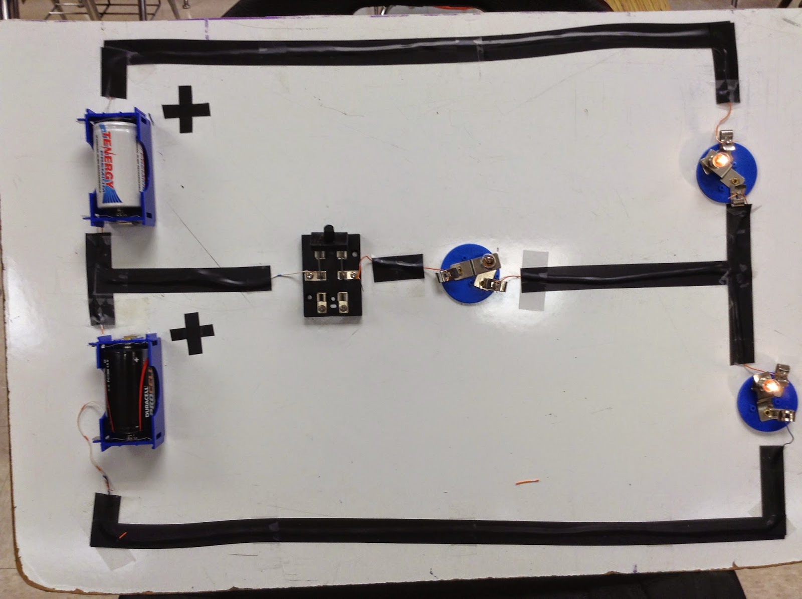
Before the middle switch was closed, both the outer light were brightly lit. Then the middle switch was closed, the middle light bulb did not turn open.

This is a more detailed explanation for how the system works.

The two batteries on the left are used to light up both the light bulb. Then when the switch is closed and a battery is introduced in the system. The additional battery did not affect the system.

This picture explains the previous picture during class.

Tuesday, October 7, 2014

Gauss's Law

September 30, 2014

This is an illustration of the flux lines.

This is one way to define flux.

We were asked which situation we would chose to do when a lighting strikes.
The professor demonstrated some stuff by putting different objects in a microwave. This is a picture of a cd in a microwave.
The sparks and flames were produced.
This is the result which burned holes on the cd.


A lit match was placed inside the microwave and it produced plasma ball, which are caused by the combustion of water vapor.

A steel wool was placed inside the microwave and it create sparks.
A light bulb was placed inside the microwave which produced different colored lights until the light bulb burned a hole and got caught on fire. A piece of soap was also placed in the microwave but due the dryness of the soap a reaction could not be seen, so a video on youtube was played to show how the soap would have reacted.
The top and bottom pictures are take from the lab manual answer the questions.


This is a solution showing how the solve the point charge is derived.